Design Keeping Common Sheet Metal Sizes in Mind
Common sheet metal material such as mild steel, galvanized steel, stainless steel, and aluminum all come in several standard sheet sizes.
Mika works with all these materials in various gauges and finishes.
If you’re unsure which metal or metals will work best for your application, contact us, we’d be happy to discuss your options.
Below are the most common sheet metal sizes used in the custom sheet metal fabrication industry. Let’s explore why designing, keeping those standard sizes in mind can maximize sheet metal production yields and lower overall project costs.
Common Sheet Metal Sizes
36” x 120”
48” x 120”
60” x 120”
72” x 120”
Note: The largest sheet size Mika’s equipment can accommodate is 60” x 120”. Some projects, depending on the size of the assembly or part, may require us to order non-standard, cut sheet sizes from our steel service center.
Design Considerations to Reduce Your Cost Per Part
It may not be obvious, but contacting your sheet metal vendor before you begin designing, while inquiring with your team whether or not an assembly or part has any “wiggle room” on overall flat size, may be the two most important things you can do at the start of any assignment.
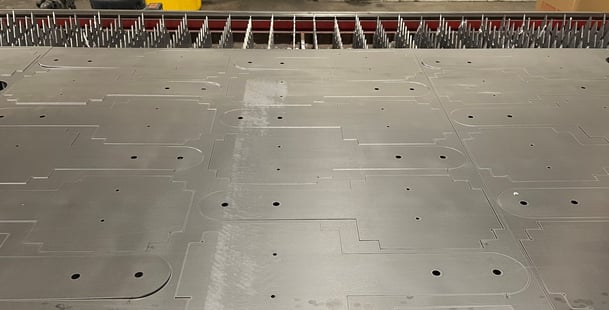
As you can see in the photo below, a single part will be duplicated multiple times up on a sheet of metal. The more sheets required to hit your total quantity, the more your overall project will cost.
Achieving the optimal size of the flat part to make the most efficient use of the sheet of metal is ideal. Knowing standard sheet sizes and running a few quick calculations before you start can make a difference on the total number of sheets of metal your project might require.
Another way to lower costs is to ask your fabricator what the optimal order quantities are. For example you may request pricing on 25, 50 or 100 pieces, but depending on the size of your part, overall size of sheet metal and which piece of equipment it will run on, a more optimal order quantity might be 32, 57 and 107. Rebecca Cole, Director of Sales and Marketing suggests, “Let your sheet metal representative know you are open to quantity suggestions because this can add up to significant savings.”

Naturally, these suggestions may be easier said than done as you and your team weigh the needs of the product specifications against the needs of designing for manufacturing (DFM). Sometimes these interests will compete; as you may often be working from specifications that include a very short list of acceptable modifications.
Regardless, your ability to present all the information so your team can make an informed decision will increase your professional credibility and may possibly increase the revenue, profitability and overall success of your company’s next product launch.
CAD Programming for Optimal Sheet Metal Cutting
A variety of different computer aided design (CAD) software programs can be used to determine the optimal sheet metal cutting pattern on a particular sheet size.
When determining the optimal layout, there are three important criteria to consider:
- What is the overall flat size of the piece to be cut?
- How much room should you allow in between parts?
- Will the parts nest or layout in a grid?
Number one is fairly self explanatory. Simply calculate the square inches of your part then divide that into the square inches of the standard sheet sizes noted above. This will help narrow down the possible sheet sizes to consider.
Next, figure out how much space is needed in between the parts. This space is critical, due to the heat generated by the cutter. If the parts are too close, they will simply fuse together and make it impossible to pull individual pieces out of the sheet. If they are too far apart you may not be optimizing the sheet properly which will add cost to your job.
While it depends on the actual gauge of your metal, a good rule of thumb for calculating the amount of space, is to multiply roughly 3 times the metal thickness you will be using. For example, if the material is 1/4” thick, you will need to leave about 3/4” around each piece. Adding this to your calculation from #1 above will further define the most likely sheet size you will require.
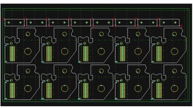
Third, based on the shape of your parts, determine if you can get more on a sheet using a grid layout (image 2 below) or nested layout (image 1 above). The difference between the two, is a grid has all the parts going the same direction while a nested layout arranges the parts in whatever layout best optimizes the sheet.
In the above photo, these parts alternately get flipped and flopped so they “nest” together and take up less space. Think about how a new pair of shoes comes arranged in a box. Putting both shoes going the same direction usually takes up more space and won’t fit the box, but when one shoe is turned so the heel butts up against the toe of the other, they fit together more tightly and take up less space. The same is true of parts on a sheet of metal. Adding this piece of information to your calculations will bring the sheet size requirement into clearer view.

While different configurations are examined during the programming stage of the custom sheet metal fabricating process to determine the very best option, you can get a pretty good idea how many parts will fit (or not) on standard size sheets using the steps above - then adjust where you can for the best fit.
According to Senior Manufacturing Engineer Kevin Timms, “The earlier a customer can involve us in their design the better. Once a project hits our department most specifications are typically set in stone. Big changes, like overall size, may be difficult to get approved at this stage and may significantly delay production.”

Not quite sure you’ve got it right? No worries, our experienced Manufacturing Engineers are here to help. Contact Us with your questions.
Related Articles:
3 Tips for Dual or Triple Sourcing Custom Sheet Metal Fabrication Jobs
Reflections on Fabtech: Manufacturing Leadership in a Time of Change

.jpg)
Comments